Well, I survived Mardi Gras, and in lieu of writing another post about C data structures, I have decided to showcase some code I wrote to simulate roll-markings using my MOPA laser engraver.
Why Standard Grayscale Engraving Fails — and How Geometry Fixes It
When engraving roll-marks with a laser, the common workflow is simple:
- White = no cut
- Black = maximum cut
- Midtones = proportional depth
This works for artistic relief.
It does not produce authentic roll mark geometry.
The issue isn’t power.
It’s shape.
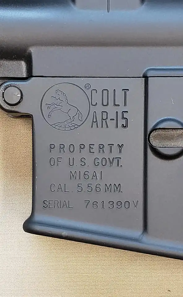
Here is a photo of an authentic roll-mark:
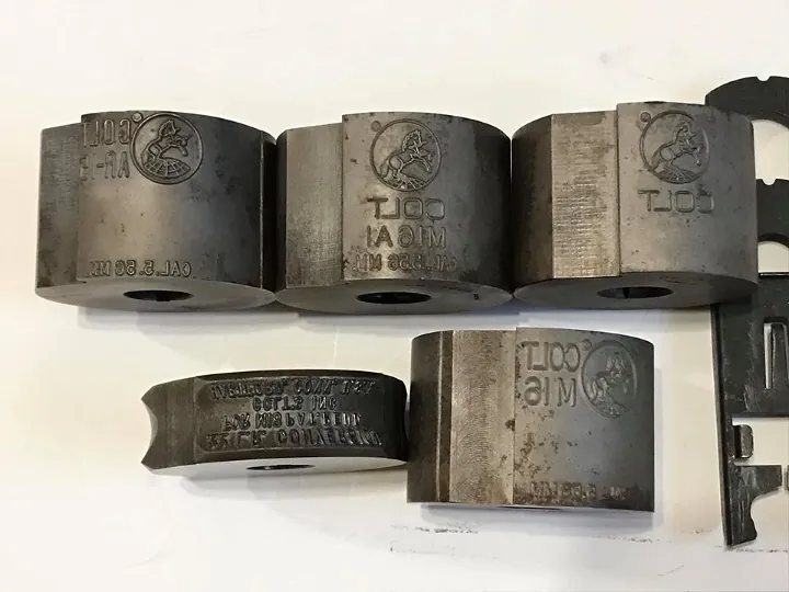
And here are the ACTUAL dies used to produce said roll-mark:
And finally, here is a photo of an MP5 build I engraved:

And here is where our problem begins…
The Hidden Assumption Behind Grayscale Engraving
Most grayscale workflows assume:
Pixel intensity directly maps to depth.
But that mapping produces a depth field — not controlled wall geometry.
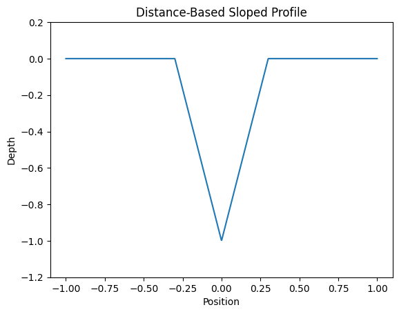
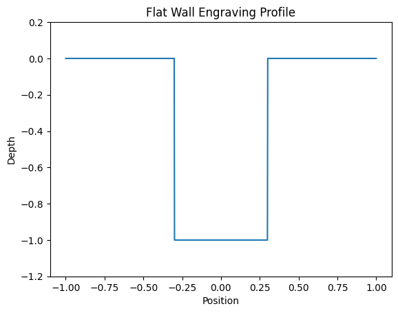
If you engrave a solid black shape using standard grayscale or binary engraving, the cross-section looks like this:

The walls are vertical.
The edge is a cliff.
The geometry is boxy.
That is not what a real stamped roll mark looks like.
What a Real Roll-Mark Looks Like
Real stamped or roll-marked engravings have controlled wall taper.
Typical cross-section:
Or more accurately, a blended geometry:

The wall is not purely vertical.
There is a transition from edge to interior.
That transition affects:
- Edge sharpness
- Shadow behavior
- Light reflection
- Perceived depth
- Authenticity
Laser engraving often fails here because as stated before, it gives us flat walls that don’t really give the effect of an authentic roll-mark.
Why Grayscale Alone Cannot Fix This
You can attempt to fake taper using gradients in the artwork itself.
But that has problems:
- Gradient width does not scale with stroke thickness.
- Depth becomes power-curve dependent.
- You lose geometric consistency in millimeters.
- Complex shapes produce unpredictable transitions.
The fundamental issue:
Grayscale encoding does not know where the edge of the shape is.
It only knows brightness.
To control wall shape, we need edge-aware depth generation.
Distance Transform as a Geometric Tool
Instead of mapping pixel intensity to depth, we can compute:
For every pixel inside the shape:
Distance to the nearest boundary.
That gives us a scalar field that describes how far each point is from the edge.
If we normalize that distance over a defined wall width, we can generate a linear inward ramp.
Mathematically:
- Let
d(x,y)be distance to nearest edge. - Let
wbe wall width in pixels. - Ramp factor
t = clamp(d / w, 0, 1) - Depth fraction
= 1 - t
Result:
- Edge pixels stay shallow.
- Interior pixels reach full depth.
- Transition width is controlled in millimeters.
This produces a physically meaningful wall taper.
Comparing Profiles
1. Binary Engraving
2. Distance-Based Ramp

3. Square + Ramp Blen
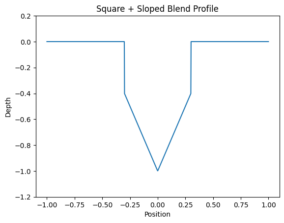
The third profile most closely resembles real roll mark geometry.
It preserves a defined vertical component while adding a controlled taper.
Controlling Geometry in Real Units
One of the key improvements is unit consistency.
Instead of defining ramp width in pixels, we define:
Wall width in millimeters.
Using export DPI:
mm = (pixels / DPI) * 25.4
That means:
- Ramp geometry scales correctly.
- Stroke thickness does not break taper width.
- The profile is material-aware.
Now geometry is independent of artwork resolution and this makes our code a lot easier to reason about.
Blending Straight and Sloped Depth
Real markings often have a square drop before taper.
We can represent total depth as:
Total depth = straight_wall_depth + sloped_wall_depth
We generate two images:
- Full-depth mask (binary ink)
- Sloped ramp (distance-based)
Then blend them proportionally:
w_full = straight / (straight + sloped)
The result is a controllable square-on-trapezoid profile.
Why This Matters Visually
When you engrave metal:
- Light grazes edges.
- Micro-shadowing enhances perception.
- Taper affects highlight width.
A vertical wall reflects differently than a tapered wall.
Even small taper changes dramatically improve authenticity.
The difference is subtle in isolation, but obvious side-by-side.
Depth Calibration and Pass Control
Laser depth is rarely linear.
Instead of relying on grayscale power mapping, we treat the grayscale output as:
A heightmap target.
Then calculate required passes using:
passes = ceil(total_depth_mm / mm_per_pass)
This decouples geometry from laser power tuning.
Now:
- Geometry is computed.
- Laser simply executes depth.
And from there, Lightburn (the software that most people use to engrave with Galvo lasers) handles the rest.
Github Repo:
To see the ACTUAL code that does all of this, click here
Yes, it is in python. The good thing about python is that its image processing libraries are really nice to work with and for that reason and that reason alone I decided to implement all of this math and logic in python. It also made getting to an MVP incredibly quick. All of this took me about a day of reasoning (lots of whiteboard shuffling and schizo lecturing to my girlfriend) and then about 2 hours to write the actual code. Put any other problem in front of me that requires actual speed and complexity and I for sure wouldn’t get within 10 feet of python.
You will also notice the lack of results photos. This is not because the code does not work, but because if I post a copy of a Colt roll-mark I did for a customer, I will get a very prompt C&D from Colt 🙂
Leave a Reply